
NodeMCU i2c
Maybe I'll explain why at some point, but I've decided to focus on Arduino for automation. Maybe you have to say Arduino IDE compatible, I'm using the NodeMCU and its variants. It's got a beefier processor than the standard Arduino, and most importantly has WiFi built in. Plus a lot more flash memory, I'm going with 4MByte at the moment. That gives me 1MByte for programs and 3MByte for a SPIFFS file system. That said, this post is about how I plan to use the i2c communications protocol. I'm doing this to instrument my Gnome Solar project, so all examples come from there.
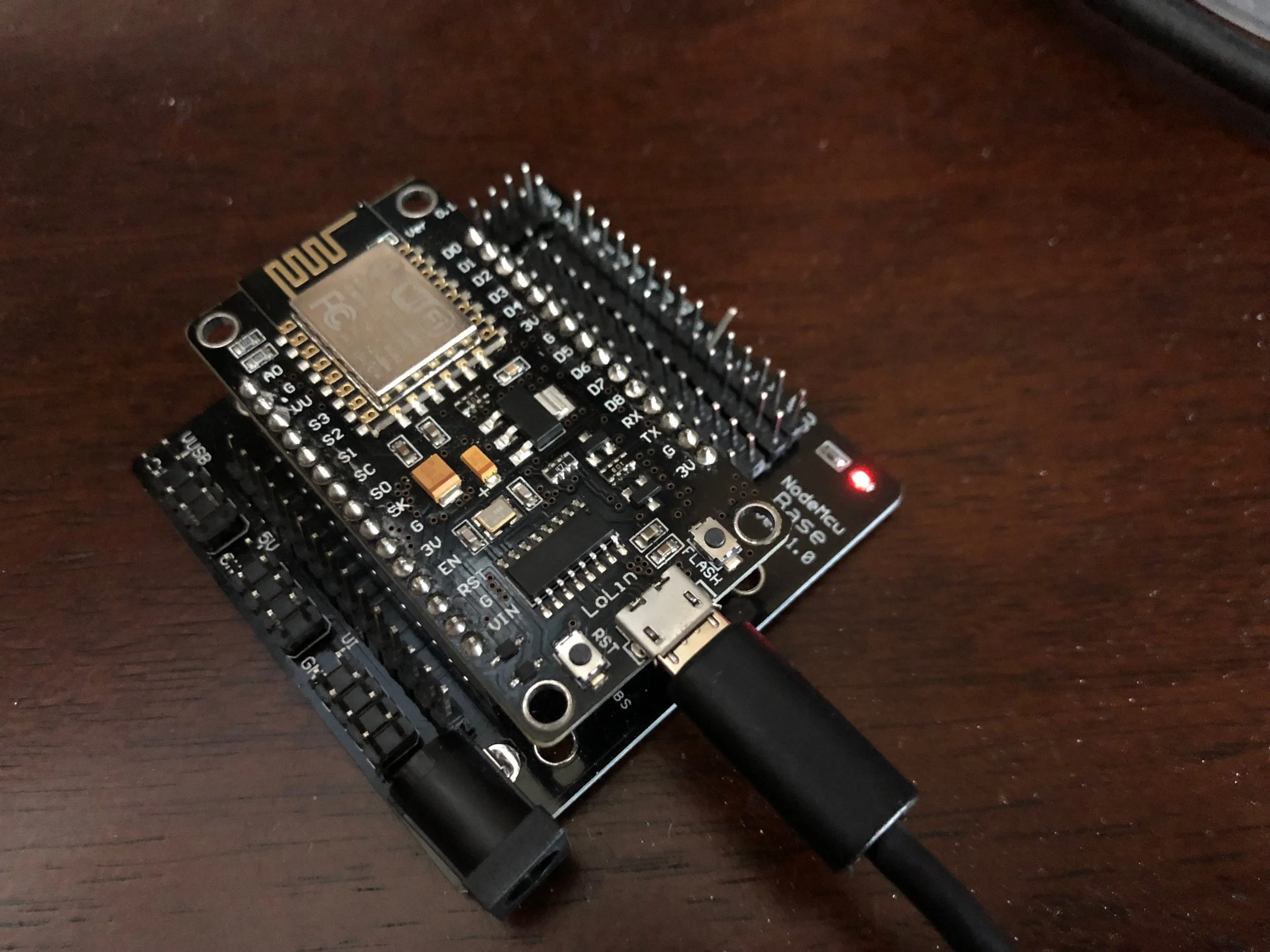
ESP8266 12E on a NodeMCU Base V1.0. It's a LiLon V3, a little funky but it fits for me. Yeah, yeah, I see the bent pin.
TODO: bust this up into separate posts
System Considerations
My goal is to monitor the health and effectiveness of my solar installation. That includes measurement of power collected by the solar panels; how much of that is getting to the battery; and what is being provided to the load(s). Both battery and solar panel efficiency is affected by temperature, and cloud cover reduces collection. These environmental conditions can be measured, or fetched from a weather service.
I'd like short term analysis on a given day, e.g. considering the morning battery voltage, and temperature/cloud cover predictions for the day, how long will my landscape lighting run tonight? Long term analysis could tell me how well my system performed over a season, or year, or span of years. That may also lead to system refinements or expansion.
Direct Measurements
First, I've got to measure voltage and current from the solar panels; to/from the battery; and to the load. All of those points are directly connected to the charge controller, and that's where I'll tap into them. I've got an extra charge controller, so I'll wire it all together and install the same connectors I've already got in place.
Here's a good place to give you a system level diagram. TODO.
Voltage Measurement
There are many voltages needing measurement, so the single analog I/O pin of the NodeMCU won't be used. Instead, I'll use an i2c connected Analog to Digital Converter (ADC). I selected a multiplexed 4-channel ADC circuit card based on the ADS1115 chip. Three of them can be easily chained and addressed using i2c so that will give me 12 voltage measurement points. It gets a little more difficult past that count.
Here's a list of interesting parameters:
- Supply Voltage: 2 - 5.5 Volts (I'll go with 5.0 Volts to match the current sensor)
- Single Ended Analog Voltage Input: Ground - 0.3V to VDD + 0.3V
- i2c levels can be shifted, but this analog voltage limit is the main reason to use the same power supply voltage as the current sensor
- Single Ended Analog Input Resistance: 10Mohm (unscaled)
- Accuracy: The chip has way more resolution than I need, and will be more affected by the way I hook this all up. Grounds and wiring will probably have more effect than characteristics of the chips. I'm not going to deeply analyze accuracy unless it turns out to be a problem.
- i2c: Since the ADC runs 5V, my i2c bus won't be compatible with 3.3V devices without level conversion. So I've included level conversion in the system such that either 3.3V or 5V processors will work.
I've got to use a 5 Volt power supply for the current measurement card (see below), so I decided to run the entire measurement system at 5 Volts. Most of these small processor boards have 3.3V gpio chips, and they tend to pass the gpio pins direct to the output. So even if you've got a processor board, you'll probably have 3.3V I/O.
Current Measurement
For current, I've chosen a specialized Hall Effect sensor. They are cheap, and don't siphon much power from the circuit being measured. It's not I2C, instead it generates an analog voltage proportional to the current being measured. I describe it since it's part of the circuit, with each analog output going to an Analog to Digital Converter (ADC) input. I bought a few of these circuit boards using the 30 Amp ACS712 chip. Here's a spec sheet for the ACS712. Here's a list of interesting parameters (including contributions from the circuit board design).
- Supply Voltage: 4.5 - 5.5 Volts
- Supply Current: 13 mA max from the chip, plus a few milliamps for the power LED
- Primary Conductor Resistance: 1.2 milli-ohm typical - resistance placed into the circuit being measured
- Zero Current Output Voltage: 1/2 power supply - allows both positive and negative currents
- Input Current: +/- 30 Amps, survival up to 5x overcurrent
- Sensitivity: typical 66 mV/Amp
- With 5 Volt power supply: 0.5 Volt output = -30A; 4.5 Volt output = +30A)
- Total Output Error: 1.5%
In summary: pretty straightforward, but I'll have to pay attention to wire size for the high current pass-through. Since I'm going to measure voltage as well as current, I decided to pop off the two pin terminal block and mount it on the main circuit board. Then to keep things level, I'll play around with the three pin header that connects to the main circuit board too.
Temperature Measurement
TBD
i2c Level Conversion
I chose the SparkFun 4 channel level converter. I haven't researched the chips they use, they are pretty simple beasts. Each side provides its own power supply voltage, so any combination of 3.3V and 5V i2c busses will work. My measurement i2c bus will go on one side, the processor's i2c will go on the other.